Connected Cat Feeder Using a Strain Gauge and an ESP32 (Video #161)
Feeding our beloved animals is a rewarding job. We do not want to forget it. So, let’s build a connected scale, which alarms us when the food bin is empty. Of course, we will be able to use the same principle to measure the weight of any other good like the honey in remote beehives, or even your own weight to visualize it somewhere in the cloud…
The usual way to measure weight is with strain gauges. Strain gauges are relatively simple devices: Thin “PCBs”, or carriers, with copper traces. These PCBs are sensitive to all kinds of forces and change their resistance accordingly.
If we stick such a strain gauge on a metal bar and apply a force to one end, the resistance of the copper traces increases or decreases, depending on the direction of the force. That’s all. In principle. You can imagine that the distances these gauges are extended are minimal if the forces are small. This is, why we have to use some tricks. But we are Tinkerers and Engineers, and we love tricks to make things work. So, the first trick is to not only place one strain gauge on the bar. We place two of better four of them on both sides of the bar. Trick number two is: We weaken the rod that it bends easier. This can be done by drilling precise holes through the bar, right under the gauges. So, with a defined force, we get a bigger movement. And trick number three uses these two or four signals from the sensors and combine them in an interesting manner. It is called the Wheatstone bridge because Sir Charles Wheatstone popularized this concept already in the 19th century. Its main advantage is its ability to measure resistors extremely accurate and it cancels temperature effects. This is exactly what we need here.
So, we combine our two or four gauges into such a bridge. Fortunately, we can buy such devices with everything mounted and connected for a few dollars. They are called “Load Cells”. These bars are made for a particular weight, for example for 2, 5, or even 40 kg. And they are announced to be very precise.
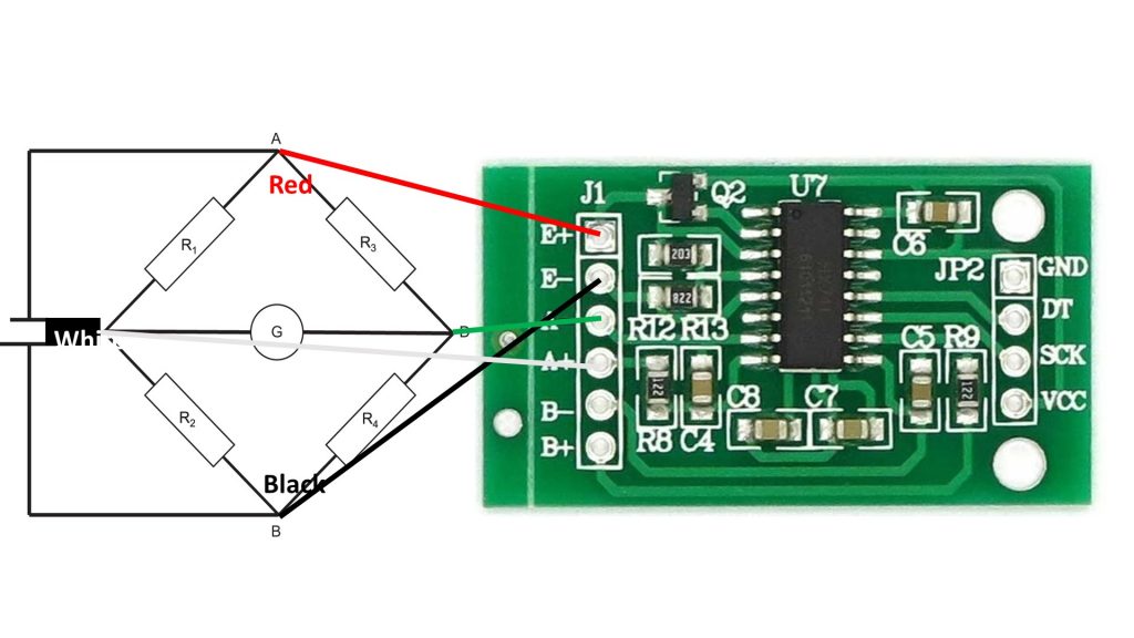
The colors of the wires seem also somehow standardized. Red, black, green, and white. If your sensor has different wire colors, you easily find which is which if you search for the wires with the higher resistance between them. These are then the opposite wires.
Now we should be able to see very small changes in voltage if we bend the metal bar. But these are really small voltages as we see here. If I bend the bar quite a lot, we only measure around 2 mV.
Now we have a Sensor to measure forces, not weight. Sir Isaak Newton, also an Englishman, also a long time ago, discovered a way to convert weight in forces and vice versa. This is what we will use now.
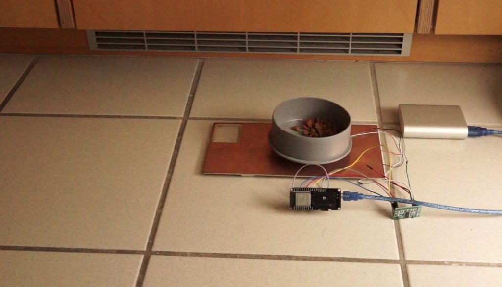
Load Cells usually have threaded holes on each side. I mount one of them to a base plate and make sure it can move a little. For this prototype, I use an old PCB which I found in my lab. Then, I mount a bowl on top of the opposite side. Like that the sensor is bent a little if I put cat food into the bowl and we should be able to measure a voltage created by this bending force. And now, the star of this video enters the scene. She is called Dishka and is always hungry. Fortunately, she has long hair, so nobody sees her belly. But even if she is hoggish we have to measure her food in grams per day. So, our bowl has to be very sensitive. And this is why we need trick number four: A very sensitive and accurate analog-to-digital converter, also called ADC. And of course, this ADC should not cost more than the cat itself…
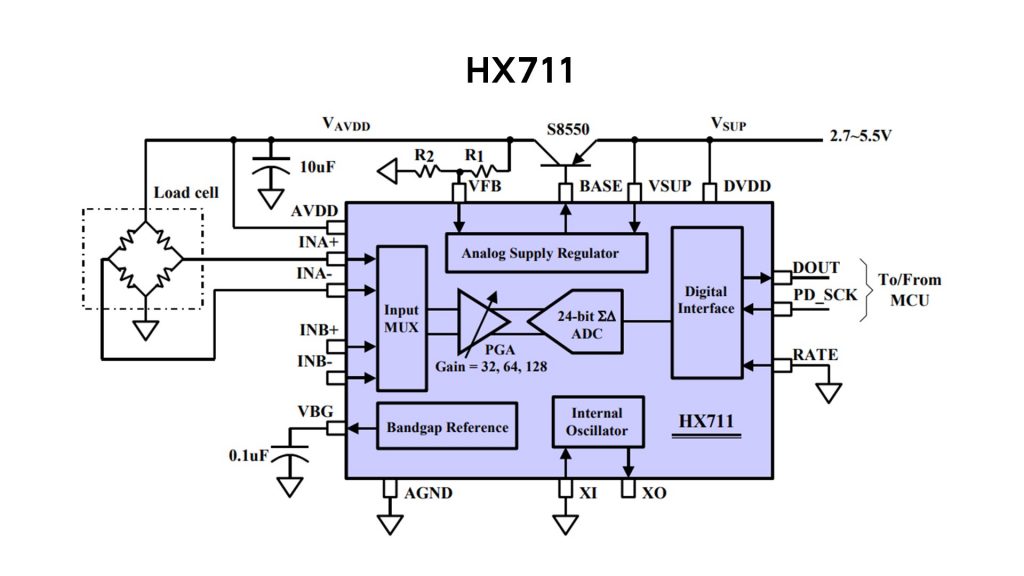
Because these days everybody is interested in measuring weight, such ADCs are produced in extremely high series. This makes it possible, that we can buy a 24-bit ADC with a built-in amplifier for a dollar if we buy a few of them. Its name is HX711. Cool. We connect the top and the bottom wires, in my case black and red, to the E+ and E- pins and the other two to A+ and A-. the B+ and B- pins are not used. Here, you could connect a second strain gauge.
Because these days everybody is interested in measuring weight, such ADCs are produced in extremely high series. This makes it possible, that we can buy a 24-bit ADC with a built-in amplifier for a dollar if we buy a few of them. Its name is HX711. Cool. We connect the top and the bottom wires, in my case black and red, to the E+ and E- pins and the other two to A+ and A-. the B+ and B- pins are not used. Here, you could connect a second strain gauge.
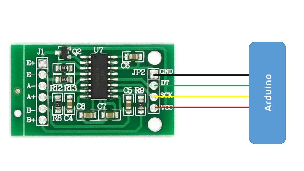
Now we only have to decide on the microprocessor and search for a library. If we want to use an Arduino Uno, we find a few libraries which work fine. We only have to connect 5V, ground, clock, and data to the respective pins, load the example sketch and are ready to go. We already see some values, and if I press the bowl, we see the values moving.
As always with scales, we first have to zero the device, and then, we have to calibrate it using a known weight.
But wait: We wanted also to get a tweet if the bowl is empty. So, we need a connected device. And because the newest kid on the block is an ESP32, I will use one of these new boards with an OLED. So, let’s check if the library works also with this new processor. The only thing we have to do is to adapt the data and the clock pins to the pins of the ESP32. I use pin25 and 26.
The HX711 also runs on 3.3 volts. So, no problem.
Unfortunately from time to time, we see outliers in the results. Not good! What is the problem? As always with intermittent problems, finding the root cause is not easy. But because we know, that it worked with the Arduino Uno, we can suspect, that it could have to do with the higher speed of the ESP32. Speed is not always good.
If we look at the timing of the two signals, we see, that the shortest signal is a little more than 100 nS. And if we look at the datasheet, we see, that this is too fast for the chip. It has to be more than 200 nS.
Usually, we can add a few delays here and there to fix this issue. Not so here, because the library uses the ShiftIn command, which reads 8 bits in a row without intervention possibility. And here, we have 3 shiftin() commands to read 24 bits in a row. So, the easiest way to solve this problem is to slow down the ESP32 chip itself. The ESP32 is a very fast chip and we can afford to slow it down for this application.
Slowing the ESP32 down is quite easy. Just include this library:
#include “soc/rtc.h”
and add this command at the beginning of the sketch:
void setup() {
rtc_clk_cpu_freq_set(RTC_CPU_FREQ_80M);
Then, our ESP32 runs with only 80 MHZ and the signal is now 3 times longer, much better for the HX711. Now, the outliers disappeared. And fortunately, the Serial speed, as well as the Wi-Fi communication, is not influenced.
The whole prototype is based on the example file of the HX711 library.
https://github.com/bogde/HX711
The sketch: https://github.com/SensorsIot/Weight-Sensors
Next, I make sure the OLED shows the values. This is very comfortable. Even if the compiler warns us, the library works with the ESP32. Now we have a nice setup to test the accuracy of our bowl. The calibration commands are included in the sketch. Please uncomment it the first time you use it.
First, this routine adjusts the sensor to zero and then waits for a defined weight to be added.
scale. set_scale();
scale.tare();
displayString(“Calibrate”, 64, 10); delay(2500);
displayFloat(scale.get_units(10), 64, 15);
The display shows: 11691
while(1==1);
Because Dishka is not interested in grams, I use cat food for calibration. I counted 50 pieces, and enter 50 as a calibration value. Now, the scale is ready to count the pieces and we can comment these lines.
This is why we take the number (11691) and divide it by the number of pieces (50). The resulting number has to be keyed in here.
scale.set_scale(233.82);
The next step is now to connect our ESP32
to the Wi-Fi network and to add the PubSub MQTT library, which works also with the ESP32. And because I already have a Raspberry Zero running Mosquitto and Node-Red, I easily can connect my new cat bowl with this system. If you do not know how to set up a Raspby for this purpose, you can watch video #126.
Because my bench light is connected to my MQTT broker, I could now switch my work light off for a moment if Dishka emptied her bowl. But we said we want a tweet. To achieve this, we add an MQTT receiver node and make sure it receives only the actual number of remaining pieces in the bowl. Then, we add a switch node to make sure, the tweet is only sent if less than 4 bites are in the bowl, a trigger which makes sure the tweet is not sent too often, and a twitter node to connect to Twitter. Done.
You find the flow also here.
https://github.com/SensorsIot/Weight-Sensors
Just copy it to the clipboard and import it from there to node-red.
Now, I get alarmed if poor Dishka is hungry.


7. January 2018 @ 19:29
Hi Andreas,
it’s very off-topic: I have bought the USB soldering iron from video “#114 Mailbag”. In general it seems to work, but I measure a constant current of 1,45 A. It does not seem to regulate its temperature (switch off). One viewer also statet in the comments to this video, that his tip began to glow. Can you maybe verify this? (I have bought it to have a fine tip to solder the RT9013 in between – until you realize the project with the “Weller tip”.)
Stefan
P.S.: I really like your youtube channel and already learned a lot from it!
11. January 2018 @ 9:17
mine draws around 1.2-1.3A and does not glow. However, it is quite hot (around 400 degrees unused)
9. March 2018 @ 18:10
Hallo Andreas,
der folgende Kommentar braucht hier nicht unbedingt veröffentlicht werden.
Ich wollte mich nur ganz herzlich für die Erwähnung in Video #187 bedanken. Auf meiner Seite habe ich direkt noch ein wenig Werbung für Deinen Kanal geschaltet 🙂
Direkt im dritten Absatz:
——————————————–
Die Leiterplatte wurde nun auch in dem sehr zu empfehlenden Youtube Kanal von Andreas Spiess kurz vorgestellt.
Mehr dazu am Ende dieser Seite.
——————————————–
Ganz am Ende:
——————————————–
Überraschenderweise wurde der Inhalt des Briefes auch gut lesbar in die Kamera gehalten. Also kann ich diesen hier nun auch (natürlich mit ein paar zensierten persönlichen Daten) veröffentlichen:
Brief
In den Kommentaren zu dem Video werde ich als “grumpy Internet troll” bezeichnet.
Das kann ich aufgrund der Tatsache das ich einen kostenlosen Youtube Kanal kritisiere durchaus nachvollziehen.
Was ich nur an dieser Stelle betonen möchte: Der Kanal ist ohne Übertreibung der beste Youtube Kanal
den ich kenne. Es war nie meine Absicht, diesen als schlecht dar zu stellen.
Auch das Experiment mit diesen zwei “Mailbag”-Videos eine Abstimmung über zukünftige Inhalte zur Verfügung zu stellen finde ich hevorragend und sehr großzügig. Die meisten Bastler machen einfach das was ihnen am meisten Spaß macht 😉
* Danach noch eine neue Kommentarsektion *
———————————
Viele Grüße
Stefan
8. January 2018 @ 19:43
Thanks for your help with this Instructable:
https://www.instructables.com/id/Solar-Weight-Based-Plant-Management-With-ESP32/
I really enjoy your videos–they are certainly the best I have ever seen for intelligent analysis of these devices.
7. April 2019 @ 8:49
Hallo,
ich verfolge seit einiger Zeit mit Interesse die Videos – einfach super.
Ich hätte eine Idee für neue Projekte:
ACS712 in Kombination mit ESP32: interessant, um “dumme” Waschmaschine “smart” zu machen. Letztlich benötigt man nicht das “volle Spektrum” der Leistungsmessung. Reicht da ein 5A Sensor aus (auch wenn die WM mehr Leistung benötigt), da man damit am unteren Ende genauer messen kann oder macht man damit die dahinter liegende Elektronik kaputt?
PS: bin kein Elektroniker wie Sie:-)
14. April 2019 @ 11:50
Der Sensor muss für die maximale stromstärke zugelassen sein, sonst kann er schmelzen. Ausserdem ist beim Umgang mit starkstrom Vorsicht geboten. Waschmaschinen arbeiten oft mit 3 Phasen (400 v)
23. May 2019 @ 9:20
hi, Andreas, thanks a lot for all your work , really nice job as usual ! regarding this IKEA weigh scale hack, you didn’t chose to use the TTGo32-LoRA board which should have been very useful (for educational purpose).
Is it because the assigned pins for hx711 are already used by the LoRa chip and no other pin can be used ?
I tried on pin 35 and 32 which seem not to be “internal feature” specific yet I had no success… which one would you suggest ?
greetings from Annecy *<8oD
24. May 2019 @ 18:57
I cannot check, but I assume you use the SPI bus for both devices. And I slow down the clock to make it compatible to the HX711 it probably needs some tinkering to get both working together. I read that the new HX711 library should be compatible with the ESP32 without the trick. Maybe you try this one and use a CS signal to select Lora or the HX711. You have to dig into the SPI bus specs for that.
27. May 2019 @ 12:23
Thanks Andreas !
I didn’t get in closer look with this new lib nor with the SPI bus things.
actually, I didn’t realized that the HX711 was also dealing with SPI , or I probably (mis)thought DO and CK could be matrixed to any other pin and starting using them with a spi.begin(clk, miso, mosi, ss) call.
but probably this is not doable as there’s only one spi driver in the ESP32 … and I need to test the CS signal instead 🙂
thanks again for your time
27. October 2019 @ 20:15
Dear Andreas! Sorry to write this duplicate comment ( I already submitted one in YouTube).
I have two questions of the HX711 interface. Is it necessary shut down and reopen the chip after every read cycle? Is is to conserve power?
Secondly I have a very nice weight cell hardware package – originally a fish weighing scale. It is however very sensitive to temperature changes (maybe it is only half bridge?). Therefore I would like to use the B channel to monitor the temperature. Does your HX711 library have a provision for channel B read?
Finally many thanks for the very informative and well produced channel and web site.
Harri
7. November 2019 @ 17:54
I think I answered on YouTube
15. June 2020 @ 9:59
hello sir,
can you help me out, i am not an arduino developer.
i am stuck at this. In the code, the loop never stops.
I want to trigger 2 relays using BLE and also set
the activetion distance area to 5meters from the esp32 so that it
triggers only when the BLE device is 5mtrs away.when it is detected
i want it to stay on, while running the code the relay switches on and
off every 2 seconds. hope you would fix it for me.
Thanks Anand.
(the code is:)
#include //Header file for BLE
static BLEUUID serviceUUID(“0000fff0-0000-1000-8000-00805f9b34fb”);
static BLEUUID charUUID(“0000fff0-0000-1000-8000-00805f9b34fb”);
String My_BLE_Address = “c1:b4:70:74:fb:66″;
static BLERemoteCharacteristic* pRemoteCharacteristic;
BLEScan* pBLEScan;
BLEScanResults foundDevices;
static BLEAddress *Server_BLE_Address;
String Scaned_BLE_Address;
boolean paired = false;
boolean chkConnet = false;
bool connectToserver (BLEAddress pAddress)
{
BLEClient* pClient = BLEDevice::createClient();
Serial.println(” – Created client”);
// Connect to the BLE Server.
pClient->connect(pAddress);
Serial.println(” – Connected”);
BLERemoteService* pRemoteService = pClient->getService(serviceUUID);
if (pRemoteService != nullptr)
{
Serial.println(” – Found our service”);
return true;
}
else
return false;
pRemoteCharacteristic = pRemoteService->getCharacteristic(charUUID);
if (pRemoteCharacteristic != nullptr)
Serial.println(” – Found our characteristic”);
return true;
}
class MyAdvertisedDeviceCallbacks: public BLEAdvertisedDeviceCallbacks
{
void onResult(BLEAdvertisedDevice advertisedDevice)
{
Serial.printf(“Scan Result: %s \n”, advertisedDevice.toString().c_str());
Server_BLE_Address = new BLEAddress(advertisedDevice.getAddress());
Scaned_BLE_Address = Server_BLE_Address->toString().c_str();
}
};
void setup()
{
Serial.begin(115200);
Serial.println(“Project-4”);
BLEDevice::init(“”);
pBLEScan = BLEDevice::getScan();
pBLEScan->setAdvertisedDeviceCallbacks(new MyAdvertisedDeviceCallbacks());
pBLEScan->setActiveScan(true);
pinMode(12, OUTPUT);
pinMode(14, OUTPUT);
}
void loop()
{
foundDevices = pBLEScan->start(3);
Serial.println(chkConnet);
if(chkConnet == false)
{
while (foundDevices.getCount() >= 1)
{
if (Scaned_BLE_Address == My_BLE_Address && paired == false)
{
Serial.println(“connecting …..”);
if (connectToserver(*Server_BLE_Address))
{
paired = true;
Serial.println(“ON”);
if(chkConnet == false)
{
digitalWrite (12,HIGH);
digitalWrite (14,HIGH);
chkConnet = true;
Serial.println(“On”);
}
break;
}
else
{
Serial.println(“Pairing failed”);
break;
}
}
break;
}
}
while (foundDevices.getCount() == 0)
{
Serial.println(“***************”);
Serial.println(foundDevices.getCount());
Serial.println(“out of range”);
paired = false;
if(chkConnet == true)
{
digitalWrite (12,LOW);
digitalWrite (14,LOW);
chkConnet = false;
Serial.println(“OFF”);
}
ESP.restart();
break;
}
}
8. March 2021 @ 15:30
Hi Andreas,
I wanted to email you but it you mention that you don’t reply to email and only comments. I figured that I would comment on this blog entry as I did something similar for my dog – it’s a water monitor in my case – http://thebraseltons.com/h2ellie/
You can click the “What is this?” In the top left corner. It was using a load cell and a Particle Photon. We have to take care of our animals!
My main reason for contacting you is that you are a sharp fellow and you enjoy ham radio stuff. I have recently become interested in fox hunting/ARDF/Direction Finding. It seems that some of the common methods are a bit antiquated and I wanted to bring it a bit to the current century. Currently, there are two main methods used today. A doppler array of antenna on the top of a vehicle is great for getting you close but then you have to use the other main method anyway – a yagi and handy talkie.
I’m using an ESP32, a BNO055 (accelerometer, gyroscope, magnetometer), and the same chip as the Baofeng UV-5R (RDA1846) for the RSSI/VSSI.
The ESP32 is transmitting the information to my iPhone using BLE and from there, I’m storing, presenting map/scan data and such. My future version of the software will allow multiple hams to join a group ID and then share the triangulation data for high speed acquisition.
I’d love to borrow some of your valuable time via Zoom/FaceTime to chat about it a bit for some feedback from someone with your experience. It has been a fun project for sure!
If you are interested, feel free to contact me and you can also delete this comment if you would like. 🙂