Variable Speed Cooling Fan for Raspberry Pi using PWM (video#138)
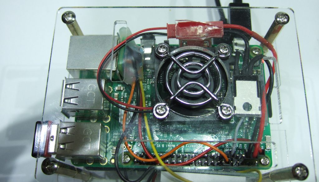
In video #131 we pimped a Raspberry Pi. One of the new features was a cooling fan which switched automatically on if CPU temperature was too high. Viewers suggested to make the speed of the fan variable. And this is, what we will do today. We also will learn a few things about Pulse Width Modulation, PID controllers, MOSFET transistors, and even a little bit of magic.
So, let’s start: in video #131 I used a simple concept: A MOSFET transistor to switch the fan on and off and a Python program which measures the CPU temperature and switched the MOSFET on, when the temperature was too high. Very simple. I used a beefy IRLZ44N transistor, because it is logic level. In video #137 I showed, that these FETs switch on at a voltage of below 2.5 volt. This is, why they are ideal for microprocessors with 3.3 volt logic.
Usually, you should add two resistors to drive a FET: R1 to discharge the gate capacitance of the MOSFET, and R2 to limit the current which is created if you change the signal at the gate. R1 is usually a few k Ohms, and R2 a few 100 ohms.
A diode should be connected in parallel to the fan, because it has an inductance and inductors create high “reverse” voltages when switched on and off fast. In our case, R1 and R2 are built into the GPIO of the Raspberry and can be omitted. The diode is not mandatory for a small fan, but it is better to include one.
The python script has two tasks. It has to be started at boot. I described how this can be done in a earlier blog and in video #131.
The python script is at the same place. You can get it with the following command:
wget http://www.sensorsiot.org/transferFiles/Pi_Zero_MQTT_Broker/fanShutdownPWM.py
Please rename it to fan_shutdown.py:
mv fanShutdownPWM.py fan_shutdown.py
Or adjust your startup file accordingly.
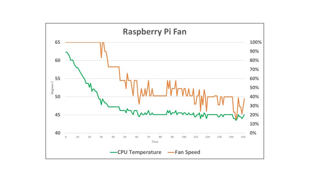
As a result, you should get a quite constant temperature of 45 degrees centigrade:
You can change this temperature on line 15 in the python file:
desiredTemp = 45 # The maximum temperature in Celsius after which we trigger the fan. If you use a different fan, it might be necessary to change the parameters of the PI controller:
pTemp=15
iTemp=0.4


22. June 2017 @ 21:27
Excuse me sir, i want to ask something
i want make project like your but i do not have IRLZ44N, i just have the brother (IRFZ44N) can i use it ? for replace the job of IRLZ44N ?
Thank for your attention
23. June 2017 @ 10:13
Just try. Maybe it works. I am not sure
16. January 2021 @ 19:19
Hello,
I also did not have IRLZ44N, so I have tried few others, and finally ended up at BS108. For my tiny 5V/0.72W fan it is just fine.
Jan
4. November 2017 @ 18:46
Love this project. It’s just what i was looking for.
And your tutorials and lessons are excellent.
Thanks.
Tzahi.
11. November 2017 @ 7:01
You are welcome!
13. November 2017 @ 16:25
Thank you for sharing all the Informations with the other makers!
I learned a lot!
Great Project(s)/Lessons!
Please go on like that!
14. November 2017 @ 7:23
Thanks, Steffen
25. December 2017 @ 6:14
Thanks alot for this. just what i was looking for. my current fan is way too noisy. i will probably need to replace that but will also implement your exercise to control the speed.
4. September 2018 @ 18:07
In your Youtube #137 you test an IRLZ44N and say that is OK for logic level switching for RasPi PWM purposes, and in Youtube #138 you also use an IRLZ44N but have a text over-writing the video at 1:02 saying IRF3708 is better, and the reason you say (in the comments) say “a low Vgs (much lower than 3.3 volts) is important”. Does this negate your test of the IRLZ44N in video #137?
I am interested in using the ESP32 to drive single or parallel (for higher total current) PWM …. perhaps you can consider doing the same sort of video as #138 but use ESP32, hardware PWM of single & multiple channels, and driving a much higher current load (instead of a fan). In that video maybe you can show both IRLZ44N and IRF3708 and explain why IRF3708 is a better choice.
Related to that ESP32 above… have you seen the http://www.M5Stack.com device? It integrates an ESP32, a color screen, 3 buttons into an expandable production-ready box. I would love to see you review it.
Keep up the great work!
9. September 2018 @ 22:50
1. You always can check the datasheets of the different FETS. The IRLZ44 worked for me under normal conditions. If I remember right, a viewer told me that the IRF3708 had a lower Vgs which is always good for our purpose
2. I have an M5stack but so far never used it. It seems a little expensive compared with other boards. I anyway print my own box for my project. So its box is not a big advantage for me.
22. December 2018 @ 15:23
Hi Mr. Andreas,
I made this using an NPN transistor (S9013) for my Raspberry Pi 3 model B+ but, I found the variable speed fan concept is noisier than the one you have shown in your video #131 (on-off control). I made a small change in the on-off controlled version. The fan will start 15 deg less temp thank the maximum temp (max temp considered 55degC), and checked that for light uses the fan will start after it stopped once, more than 30min.
I will be very happy if you provide some tips/suggestions regarding noise reduction.
Thank you very much for your swiss (I thought sweet) accent and informative videos.
22. December 2018 @ 15:26
Hi,
I think you have to experiment what is ok for you. These small fans are quite noisy if they have to work 😉
14. April 2019 @ 11:56
I assume the noise comes from the fan (if your PWM frequency is high enough). So the only possibility is to change the fan. Silten fans are quite expensive 🙁
7. March 2019 @ 8:37
Thanks greatly for such an usefull project, but on my PI3 it isn’t working properly. When I switch on my PI, the fun is running during 3-5 seconds, after this the one swith off.The PI is switching off afer 1-2 minuts. I will using siple resistor for speed control.
14. April 2019 @ 11:54
Strange. It worked for many people.
9. March 2019 @ 20:51
Hi Andras, I enjoy your channel. Thank you. Your esp32 work has helped me greatly. I’ve created an over the top high performance raspberry pi case out of billet aluminum and carbon fiber. I wanted to make a case that didn’t cut corners. Check it out https://www.youtube.com/watch?v=hM_7OLqvmWI
Be sure to check out my simple hack to add a power switch.
14. April 2019 @ 11:52
Nice case!
28. May 2019 @ 11:17
If you do not mind, made some changes in the code.
https://github.com/sheriff02/RaspberryPy
16. July 2019 @ 17:01
i used an alternative, IRFZ44N and nothing happen.. fan not working.. i have to use exactly IRLZ44N?
regards..
16. July 2019 @ 18:05
You need a transistor which switches on at 3.3 volts. The IRFZ44N starts at about 4 volts. So it stays always off.
2. October 2019 @ 12:57
Hi Andreas,
I’m watching your YouTube channel frequently.
Inspired by it I want to cool my Raspberry Pi 4 with a 120mm FAN.
The Fan that I would like to use is
https://www.arctic.ac/eu_en/arctic-f12-pwm-co.html
by specification if needs 12V DC. To provide such power I’m thinking of using MT3608 Boost Converter.
As source of power what would you recommend: GPIO 5V or USB 2.0?
As this FAN can be controlled with PWM Signal on Pin 4, my presumption is that I will be able to control it with your python script. Correct?
Pin 3 on the FAN is “RPM Signal”. To read the fan speed can it be connected directly to a GPIO pin or additional elements are needed?
2. October 2019 @ 14:48
1. Maybe 12 cm is a little too big, at least much bigger than the board.
2. If you look at the specifications you can run it also with 5 volts if you want
3. You should be able to use the PWM signal, but I am not sure because I did not see any specifications.
31. October 2019 @ 22:45
thanks for this great video.
i used it to implement a fan control for my raspberry pi 4 with a “Noctua NF-A4x10 FLX 5V” fan. Unfortunately, the fan starts only at a fanspeed of about 70. That’s why I added the following to the code:
def Anlaufen():
myPWM.ChangeDutyCycle(90)
sleep(0.2)
myPWM.ChangeDutyCycle(fanSpeed)
return()
…
def handleFan():
if fanSpeed>30<35:
Anlaufen()
This is how my fan starts to spin earlier. Once he is in motion everything is ok. since i'm not that good at python this solution is workable for me. maybe you have a better one?
7. November 2019 @ 17:53
If the solution works I would keep it. I am no Python specialist either…
21. February 2020 @ 15:00
Hi,
Ein Hollander hier.
Werde in English weiter schreiben weil vielleicht verstehen sie mein Rudi Carrell Deutsch nicht und die rest von die welt sicher nicht. 😉
IT WORKS !!!
However it makes a bit of 50Hz noise (maybe implementing Voltage level control with a transistor and some resistors is an option, no PWM). Next project for me is to incorperate the ambient temp (via snmp, got a Zabbix server running) in the python script, instead of the constant maxTMP, that should be fun !! 🙂
Thank you for the explanation.
I think the very good thing about your “practical lessons/videos” is that you give relevant extra info.
Showing the datasheet of the FET transistor, schottky diode, and so on are good examples of this.
So.. Thanks again!!!
3. December 2020 @ 23:20
Thanks for this – much better than just plugging it into 5v and letting it always run!
Do you mind if I adapt your script to run as an OctoPrint (https://octoprint.org/) plugin?
An idea for a small improvement – instead of cutting of the fan at min_speed (15 in your example) you could scale it from min_speed to 100% something like:
fanspeed = min_speed + (((100-min_speed)/100))*(pDiff +iDiff))
15. December 2020 @ 3:52
so what is the final value for R1? the diode can be a 1N4148?